What is Cardiac Fibrillation
Ventricular Fibrillation is an extreme cardiac emergency due to asynchronous contraction of the coronary muscles. This uncoordinated movement of the ventricle walls of the heart might result from coronary problems, from electric shock or from abnormalities of body chemistry. Because of this irregular contraction of the muscle fibers, the ventricles simply vibrate rather than pumping the blood effectively. This result in steady fall of cardiac output and can be deadly if steps aren’t taken promptly.
Understanding Cardiac Defibrillator
Ventricular fibrillation can be changed into a more efficient rhythm by applying a high energy shock to the heart. This sudden surge across the heart causes all muscle fibers to contract simultaneously. Possibly, the fibers may then respond to normal physiological pace making pulses. The instrument for administering the shock is called a cardiac defibrillator. The shock may be introduced to the heart via electrodes located at the chest of the patient(external defibrillation) or the electrodes can be held against the heart while the chest is open (internal defibrillation). Higher voltages are required for external defibrillation than for internal defibrillation. Implantable defibrillates are also available for patients who are at high risk of ventricular fibrillation.
DC Cardiac defibrillator
In almost all present-day transthoracic cardiac defibrillators, an energy storage capacitor is charged at a relatively slow rate from the AC line by mean of a step-up transformer and rectifier arrangement or from a battery and a DC to DC converter arrangement.
Circuitry of Cardiac Defibrillator
The basic circuit diagram of a DC cardiac defibrillator has A variable auto-transformer T1 forms the primary of a high voltage transformer T2. The output voltage of the transformer is rectified by a diode rectifier and is connected to a vacuum type high voltage change-over switch.
In position A, the switch is connected to one end of an oil-filled 16 micro-farad capacitor. In this position, the capacitor charges to a voltage set by the positioning of the auto-transformer.
When the shock is to be delivered to the patient, a foot switch or a push button mounted on the handle of the electrode is operated. The high voltage switch changes over to position ‘B’ and the capacitor is discharged across the heart through the electrodes.
In a cardiac defibrillator, an enormous voltage (approx. 4000 V) is initially applied to the patient. It has been shown by various investigations that although short-duration pulses (as low as 20 μs), can affect defibrillation, the high current required impairs the contractility of the ventricles.
This is overcome by inserting a current limiting inductor in series with the patient circuit. The disadvantage of using an inductor is that any practical inductor will have its own resistance and dissipates part of the energy during the discharge process. In practice, a 100 mH inductor will have a resistance of about 20 W. The energy delivered to the patient will, therefore, be only 71% of the stored energy.
The inductor also slows down the discharge from the capacitor by the induced counter voltage. This gives the output pulse a physiologically favorable shape. The shape of the waveform that appears across electrodes will depend upon the value of the capacitor and inductor used in the circuit.
The discharge resistance which the patient represents for the defibrillating pulse may be regarded as purely ohmic resistance of 50 to 100 ohm approximately for a typical electrode size of 80 cm2. The shape of the current/time diagram of the defibrillating pulse remains largely unchanged in the above resistance range, except for a change in amplitude which depends on the resistance.
Cardiac Defibrillator Electrode
There are two general classes of waveforms used in cardiac defibrillator: mono-phasic and biphasic. Monophasic waveforms use escalating high levels of energy delivered in one direction through the patient’s heart whereas a biphasic waveform delivers energy in both directions. The biphasic waveform is preferred as it has proven in clinical studies to defibrillate more effectively than other types of waveforms.
It has been found experimentally that the success of defibrillation correlates better with the amount of energy stored in the capacitor than with the value of the voltage used. It is for this reason that the output of a DC defibrillator is always calibrated in terms of watt-seconds or joules as a measure of the electrical energy stored in the capacitor. The instrument usually provides output from 0–400 Ws and this range provides sufficient energy for both external and internal defibrillation.
Energy in watt seconds is equal to one half the capacitance in farads multiplied by the voltage in volts squared, i.e., E = 1/2 CV2. If a 16 microfarad capacitor is used, then for the full output of 400 Ws to be available, the capacitor has to be charged to 7000 V. For internal defibrillation, energies up to 100 Ws are usually required whereas higher energy levels are necessary for external defibrillation. The DC defibrillator cannot be used for rapidly repeated shocks because it requires about 10 s to recharge the capacitor.
Cardiac Defibrillator Synchronizer
In this case, the pump action of the ventricles still exists. However, at defibrillation of a heart in auricular fibrillation, the shock may bring the ventricles into fibrillation. There is, however, a period in the heart cycle in which the danger is least. Defibrillation must take place during that period. This is called Cardio-version. In this technique, the ECG of the patient is fed to the defibrillator and the shock is given automatically at the right moment.
The function of the synchronizer circuit is to permit placement of discharge at the right point on the patient’s electrocardiogram. The application of the shock pulse during the vulnerable T wave is avoided, otherwise there is a likelihood of producing ventricular fibrillation. With the synchronizer unit, the shock is delivered approximately 20 to 30 ms after the peak of the R wave of the patient’s ECG.
The synchronizer unit contains within it, an ECG amplifier which receives the QRS complex of the ECG and uses this to trigger a time delay circuit. After an interval of the desired delay time (approximately 30 ms), the defibrillating capacitor is discharged across the chest through the electrodes.
Automated External Cardiac Defibrillator
An important development in the field of cardiac defibrillators has been the development and successful use of smart automatic or advisory external defibrillators (AEDs) which are capable of accurately analysing the ECG and of making reliable shock decisions. They are designed to detect ventricular fibrillation with sensitivity and specificity comparable to that of well-trained paramedics, then deliver (automatic) or recommend (advisory) an appropriate high energy defibrillating shock.
The block diagram of an automated external defibrillator (AED), which is a highly sophisticated microprocessor-based device that monitors, assesses and automatically treats patients with life-threatening heart rhythms. It captures ECG signals from the electrodes, runs an ECG analysis algorithm to identify shockable rhythms, and then advises the operator about whether defibrillation is necessary.
Implantable Cardiac Defibrillator
The use of automatic implantable defibrillators (AID) is recommended for patients who are at high risk for ventricular fibrillation. This is a small match box sized device that can be implanted in the body: in the chest or abdomen. It can constantly monitor the heart rhythms, and deliver the necessary electrical impulse before the disrupted rhythms translate to a cardiac arrest.
An implantable cardiac defibrillator is continuously monitors a patient’s heart rhythm. If the device detects fibrillation, the capacitors with in the device are charged up to 750 V. The capacitors are then discharged into the heart which mostly represents a resistive load of 50 ohms and to bring the heart into normal rhythm. This may require delivery of more than one high energy pulse. However, most devices limit the number of high energy shocks to 4 or 5 during any single arrhythmic episode. The shock duration for efficient defibrillation is approximately 30–35 J at 750 volts.
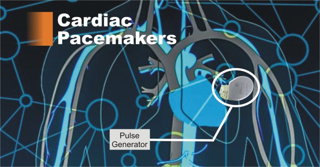
The basic components of an implantable cardiac defibrillator are a battery, a capacitor to store and deliver charges, a microprocessor and integrated circuits for electrogram sensing, data capture, storage and control of therapy delivery, a header to connect the endocardial leads used for sensing, pacing and defibrillation. All these components together are called a pulse generator and are encased in a titanium can.
Left ventricle assistive device
The left ventricle is the large, muscular chamber of the heart that pumps blood out to the body. A left ventricular assist device (LVAD) is a battery-operated, mechanical pump-type device that’s surgically implanted. This device is used on people awaiting a heart transplant before a suitable heart becomes available.
It has a tube that pulls blood from the left ventricle into a pump. The pump then sends blood into the aorta which is the large blood vessel leaving the left ventricle. This effectively helps the weakened ventricle. The pump is placed in the upper part of the abdomen. Another tube attached to the pump is brought out of the abdominal wall to the outside of the body and attached to the pump’s battery and control system.
Types of Leads and Electrodes
Two types of electrode systems are commonly used, bipolar and unipolar.
In the unipolar system, one electrode is inside or on the heart and is the stimulating electrode, and the second electrode (indifferent electrode) is usually a large metal plate attached to the pulse generator.The indifferent electrode is much larger in size than the pacing electrode. The current in this case flows between the pacing electrode in the heart and the indifferent electrode via the body tissue. The batteries are so arranged that the pacing electrode is negative (cathode) and the indifferent electrode is positive (anode).
In the bipolar electrode system, both electrodes are approximately of the same size and both are placed inside or on the heart, so that the current flows between the two electrodes. The pulse generator is so attached that the distal electrode, at the tip of the catheter, is negative and the proximal electrode ring is positive.
A typical unipolar lead used for permanent stimulation of the heart consists of two parts: the electrode and the lead. The proper negative heart electrode is represented by the platinum-iridium (Pt-Ir) catheter tip and has a length of 2 mm and diameter of 3 mm. The tip is connected to a connecting lead, a Pt-Ir specially wound wire completely embedded in silicon rubber. The outer diameter of the lead is 3 mm and its length is about 125 Two types of electrode systems are commonly used, bipolar and unipolar.
In the unipolar system, one electrode is inside or on the heart and is the stimulating electrode, and the second electrode (indifferent electrode) is usually a large metal plate attached to the pulse generator.
The indifferent electrode is much larger in size than the pacing electrode. The current in this case flows between the pacing electrode in the heart and the indifferent electrode via the body tissue. The batteries are so arranged that the pacing electrode is negative (cathode) and the indifferent electrode is positive (anode).
In the bipolar electrode system, both electrodes are approximately of the same size and both are placed inside or on the heart, so that the current flows between the two electrodes. The pulse generator is so attached that the distal electrode, at the tip of the catheter, is negative and the proximal electrode ring is positive.
cm. The silicon-rubber core in the spiral gives the lead an excellent mechanical sturdiness.
Once the pulse generator and the lead are in place, the electrode-tip which comes in contact with the endocardium or myocardium creates a dynamic process involving physiological changes at the electrodes. A fibrous tissue encapsulates the electrode which increases the stimulation threshold. This process continues for approximately one month during which period, the electrode stabilizes within the fibrous capsule.
The electrodes for delivering stimulating pulses can be connected either on the outside or inside wall of the heart. Electrodes connected to the outer wall of the heart muscle are called myocardial electrodes which are connected to the inner side of the heart chamber are known as endo-cardiac electrodes.
Conclusion
Cardiac Defibrillators are devices that provide an electric charge or current to the heart to restore a normal heart rhythm. If the heart rhythm stops due to cardiac arrest, a cardiac defibrillator helps it to regain it’s beating. An internal cardiac defibrillator is generally needed for people at high risk of cardiac arrest due to a ventricular arrhythmia. People with heart failure having problems with the contraction of the heart, such as abnormal left ventricular ejection fraction. The main difference between a pacemaker and a cardiac defibrillator is that the pacemaker gives frequent and more subtle regulation of the heartbeat whereas a cardiac defibrillator provides a shock when the heart’s function is dangerously abnormal.